Voltage Divider Calculator: Vout, Loaded Dividers, and E24 Reverse Solving Made Simple
Free online voltage divider calculator. Compute Vout from Vin, R1, and R2 with current and per-resistor power, model loaded dividers with RL, and reverse-solve R2 for a target voltage with E24 standard values. 100% client-side.
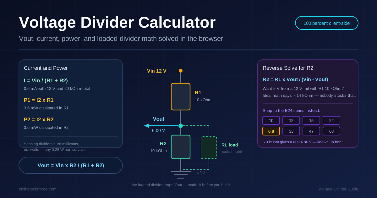
Table of Contents
Voltage Divider Calculator: Vout, Loaded Dividers, and E24 Reverse Solving Made Simple
The voltage divider is the first circuit every maker meets — two resistors and a promise that one line of arithmetic turns any voltage into any other. It is also the first circuit that misbehaves under load: ask it to power something and the output collapses, so the 6 V rail you designed reads 4 V on the multimeter.
The free voltage divider calculator handles that math in both directions: forward mode computes Vout from Vin, R1, and R2 with current and per-resistor power, a loaded-divider model adds RL in parallel with R2, and reverse mode solves for R2 from a target voltage with E24 snapping. All math runs 100% client-side, updating live as you type.
Why Use Voltage Divider Calculator?
- Two directions, one tool: compute Vout from known parts, or solve for R2 from a target voltage — how real designs begin.
- Loaded-divider modeling: attach RL in parallel with R2 and watch the output sag, so "6 V" never surprises you as 4 V.
- Current and power readouts: see the dissipation in each resistor so a 0.25 W part never cooks silently.
- E24-aware reverse solving: ideal math says 7.14 kΩ; the tool snaps to a buyable 6.8 kΩ and shows the real result.
- Instant and private: everything runs client-side with live updates — nothing is uploaded or tracked.
Key Features
| Feature | What It Does |
|---|---|
| Forward solve | Computes Vout, divider current, and power in R1 and R2 |
| Loaded divider model | Adds RL in parallel with R2 and recomputes the true output |
| Reverse solve | Finds R2 for a target Vout and snaps it to E24 standard values |
| Actual vs target readout | Reports the real output after snapping, including the loaded case |
| Client-side operation | Runs entirely in the browser; nothing is sent to a server |
- Mode switching is instant — compare nominal and loaded behavior in seconds.
- The power readout doubles as a wattage sanity check before ordering parts.
How to Use
- Run a forward calculation. Enter Vin, R1, and R2 — say 12 V, 10 kΩ, 10 kΩ — and instantly read Vout, divider current, and per-resistor power.
- Read the supporting numbers. Note the 0.6 mA current and 3.6 mW per resistor — proof a divider senses, not supplies.
- Model the load. Enter RL and watch the output: a 10 kΩ load on that divider drags 6.00 V down to 4.00 V.
- Reverse-solve for R2. Switch to reverse mode, enter a target Vout, and the tool solves for the required resistance, snapped to the nearest E24 value.
- Verify the actual result and build. A 5 V target on a 12 V rail with R1 10 kΩ lands on 6.8 kΩ delivering 4.86 V — decide if that is close enough.
The Formula and the Loaded Trap
The basic formula
Two resistors in series across the supply, output taken at the junction:
Vout = Vin × R2 / (R1 + R2)
The output is the fraction of total resistance R2 represents. With Vin = 12 V and R1 = R2 = 10 kΩ, Vout = 6.00 V; raise R2 to 22 kΩ and it climbs to 8.25 V.
Current and power in each resistor
The same current flows through both resistors:
I = Vin / (R1 + R2)
For the 12 V, 20 kΩ example that is 0.6 mA, so each resistor dissipates P = I² × R — just 3.6 mW, safely inside any 0.25 W rating.
The loaded-divider trap
Connect a load RL and it parallels R2, so the effective bottom resistance becomes (R2 × RL) / (R2 + RL) — always smaller, so the output sags.
Attach a 10 kΩ load to that divider: the parallel combination is 5 kΩ, so Vout = 12 × 5/15 = 4.00 V — a one-third collapse from a load that "should not" matter. A microamp MCU input barely moves the needle; a relay coil or LED does. Modeling RL up front makes this classic mistake a five-second check.
Reverse-solving R2 with E24 values
Designs start from requirements, not parts on hand. Rearranged:
R2 = R1 × Vout / (Vin - Vout)
To get 5 V from a 12 V rail with R1 = 10 kΩ, ideal math says 10 × 5/7 = 7.14 kΩ — a value in no parts drawer. The solver snaps to the nearest E24 value, 6.8 kΩ, and recomputes the real output: 12 × 6.8/16.8 = 4.86 V, known up front.
Divider or regulator?
Dividers sense; regulators power. Use a divider where load current is negligible — scaling a sensor, biasing a transistor, feeding an ADC. When real current at a stable voltage is required, use an LDO or switching regulator; every milliamp drags the output down.
Practical Use Cases
Sensor voltage scaling
A 5 V sensor feeding a 3.3 V ADC needs scaling: through a 10 kΩ and 15 kΩ divider the signal lands at 3.0 V — safely inside range with reasonable source impedance.
Potentiometer wiring
A potentiometer is a mechanically adjustable voltage divider: ends to supply and ground, wiper as Vout. This explains why a 10 kΩ pot drives headphones poorly but feeds a high-impedance volume control beautifully — loaded-divider math wearing a knob.
Bias networks
Transistor stages use divider bias to hold the base at a set operating point, with divider current roughly ten times the base current for stability — easy to verify in the tool.
Level-shift education
A divider dropping a 5 V logic signal into a 3.3 V input works for slow, one-direction signals. Walking the numbers shows the limits: output impedance rises, edges slow, and fast buses misbehave — why proper level shifters exist.
Best Practices
- Keep divider current roughly ten times the load current. That ratio holds the output near nominal as the load varies.
- Never power a load from a divider. Use it to reference and sense; use a regulator for anything drawing real current.
- Budget for resistor tolerance. Two 5 percent parts at their worst edges swing a nominal 6.00 V output between 5.56 V and 6.30 V unloaded.
- Check the input impedance of whatever reads Vout. The reading device is itself a load — its resistance belongs in the RL field.
- Watch the power readout when shrinking resistance. Stiff dividers trade stability for heat; stay well under each rating.
- Trust the E24-snapped actual output, not the ideal target. The bench measures the snapped value, so design against it.
Design Your Next Divider With Confidence
Two resistors look trivial until a load shows up and the math stops matching the multimeter. Open the voltage divider calculator, model your load, and let E24 snapping hand you real, buyable values with honest output numbers.
Related Tools You Might Like:
- LED Resistor Calculator — size the current-limiting resistor for your LEDs.
- Ohm's Law Calculator — verify voltages, currents, and power anywhere in a circuit.
- 555 Timer Calculator — turn timing targets into astable and monostable circuits with E24-snapped parts.
Happy building!
Frequently Asked Questions
Q: What is a voltage divider used for?
A: It produces a known fraction of an input voltage for sensing and referencing — scaling sensor signals, biasing transistors, setting references. It is not a power supply: load current pulls the output down.
Q: Why does my divider output drop when I connect a load?
A: The load parallels R2, shrinking the effective bottom resistance. On a 12 V, 10 kΩ plus 10 kΩ divider, a 10 kΩ load turns the bottom leg into 5 kΩ and drops the output from 6.00 V to 4.00 V.
Q: What are E24 values and why does the tool snap to them?
A: E24 is the standard preferred-value series — the digits 10, 12, 15, 22, 33, 47, and 68 repeated in every decade. Suppliers stock them everywhere, and the tool recomputes the actual output from the snapped value.
Q: Does the calculator send my values anywhere?
A: No. Every computation runs client-side in your browser — nothing is uploaded or stored, and the tool works offline once loaded.